

Control panel
Every button, indicator and main screen on the TIS Tronic 260U — START, STOP, UP, DOWN and F, plus the alarm, pump and fan indicators.
Six buttons and four indicators run the whole controller: hold F for three seconds to enter the menu, press F briefly to cycle between main screens. Everything else follows from those two gestures.
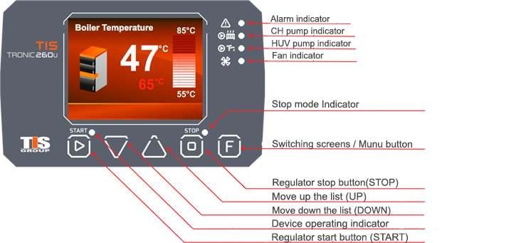
Indicators
| Indicator | Meaning |
|---|---|
| Warning / alarm | A malfunction — overheating, or a damaged temperature sensor (short circuit or breakage). Pulses red |
| CH pump | The central heating pump is running |
| HUW pump | The hot water pump is running |
| Fan | The fan is in operation. Glows until the set temperature is reached, and during purge operation |
| START | Flashing — ignition in progress. Constant — automatic operation mode |
| STOP | The device is stopped. Yellow, constantly illuminated when inactive |
Buttons
Press briefly in normal operation to cycle through the main screens and observe the heating and hot water modules.
Hold for 3 seconds to enter the controller menu.
When editing a parameter, pressing F exits configuration mode.
Switches the controller to the operating state.
In manual mode, turns a connected mechanism on and off.
In the menu, on a YES screen, enters and edits the selected parameter, and confirms changes afterwards.
Stops the controller from the main temperature screens, and turns off connected devices in manual mode.
In the menu, on a NO screen, cancels the selected parameter without saving. Pressing it again returns one level up.
Also used to reset alarm warnings.
Navigate the menu, and increase or decrease the value of the selected parameter by one unit per press.
Press and hold to change the value faster.
Reading a screen
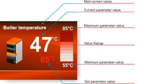
| Element | What it shows |
|---|---|
| Main screen name | Which reading you are looking at — boiler, exhaust gas or HUW |
| Current parameter value | The large figure: the live measurement |
| Set parameter value | The smaller orange figure: the target |
| Maximum parameter value | Top of the bar — the upper end of the adjustable range |
| Minimum parameter value | Bottom of the bar — the lower end of the adjustable range |
| Value range | The bar itself, filled to the current reading |
Main screens
Press F briefly to rotate through the main screens.
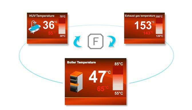
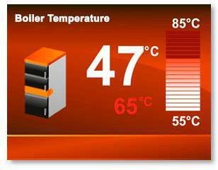
Boiler temperature screen
Exhaust gas temperature screen
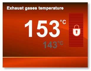
Inactive screens
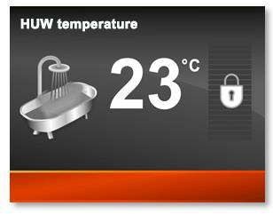
Changing the setpoint takes no menu
On the boiler temperature main screen, UP and DOWN change the boiler setpoint directly. The
same is true of the hot water setpoint on the HUW main screen.
Powering up for the first time and working through the initial setup.
TIS Tronic 260U overview
What the TIS Tronic 260U controller does on a UNI 60 — fan modulation, pump control, three operating modes, hot water preparation and the safety chain behind it.
First start
Power up the TIS Tronic 260U for the first time and work through the six initial settings — operating mode, fan type, pump start temperature, exhaust sensor and more.